
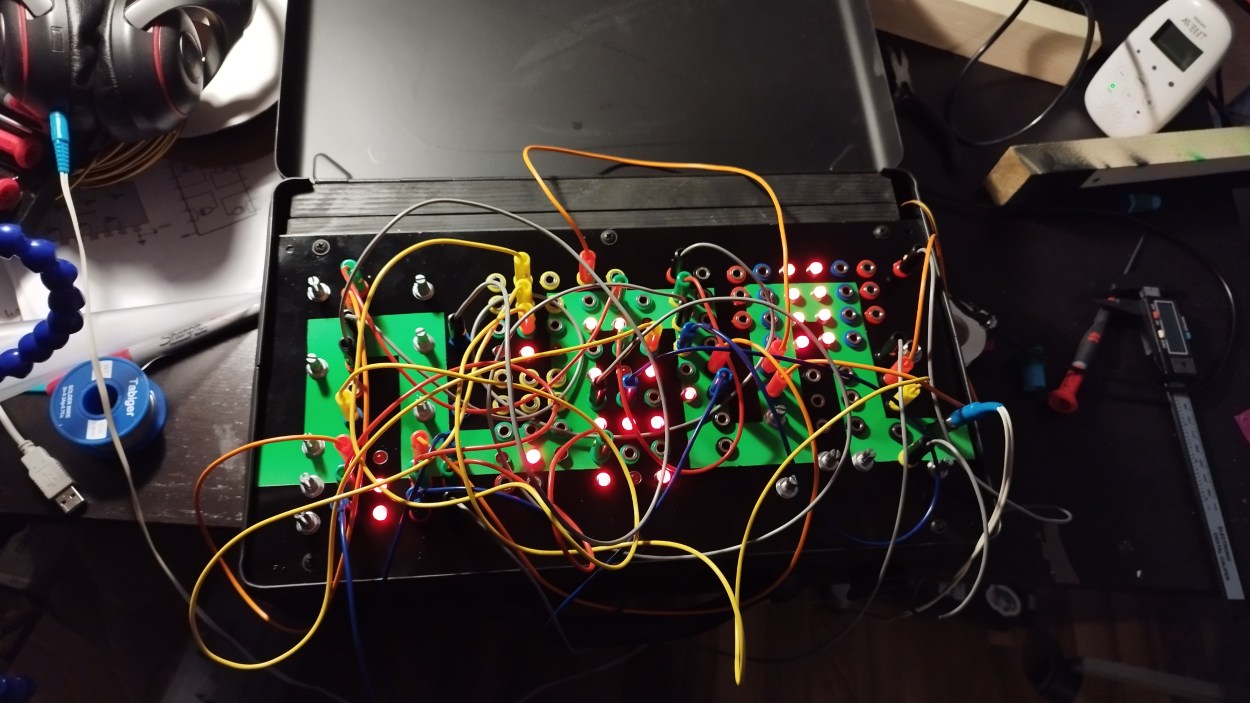
I know the title suggests that there will be another version of this and as I cannot deny that I would like to build at least some extension of this I’m pretty sure I won’t do it in the same format because the offboard wiring was extensive to say the least.


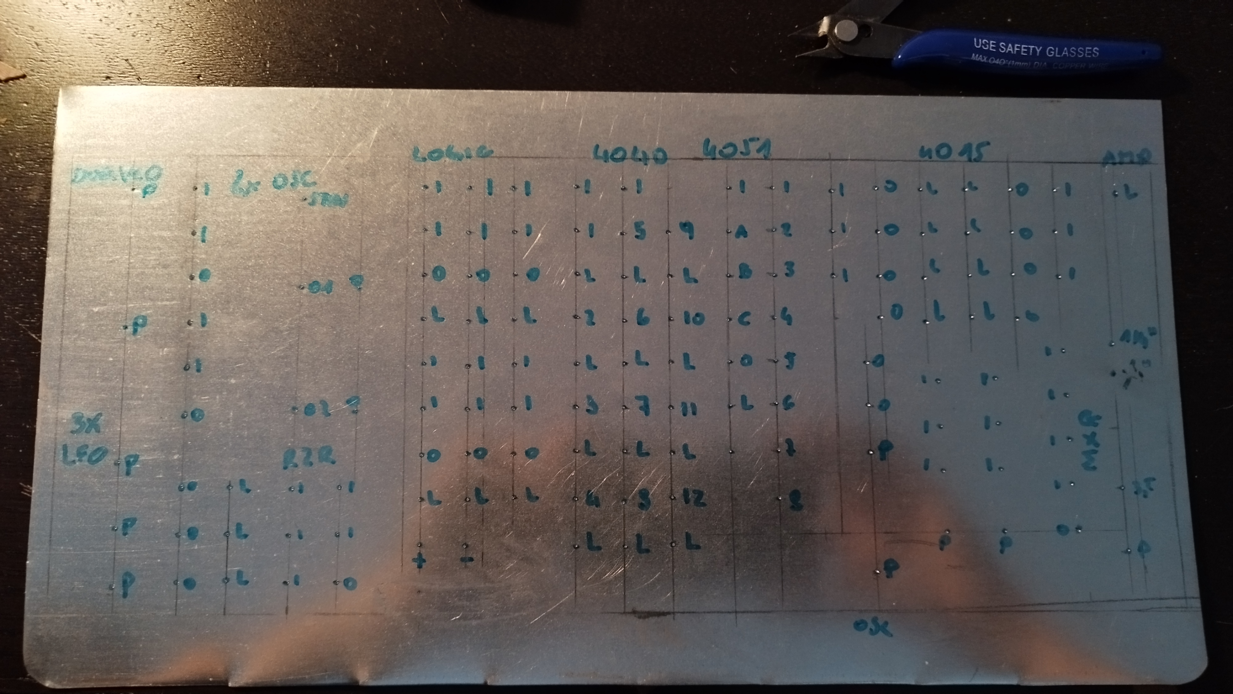
As the 4015 died on me I swapped it for a 4017. Now the layout obviously didn’t change.
Schematics
I did approximately three weeks of research before I decided on what ICs I want to use in which configuration and in the end I can tell you it’s not even remotely what I have imagined it to be. But nonetheless it’s a fun thing to play around with.
I was mostly inspired by stuff on electro-music.com and hackaday (logic noise)
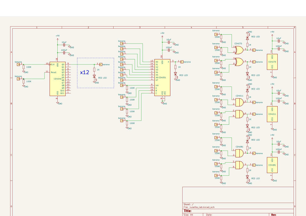
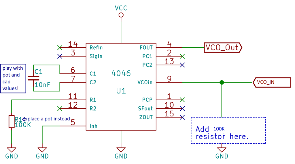
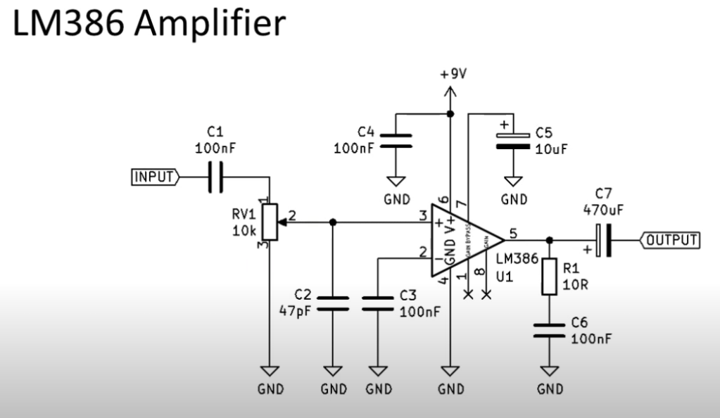
I know there are some pieces missing but you find everything you need to know here and in the datasheets of the ICs used/you wanna use.
