
After about a year with the old design I wanted to revisit it and try to work out its flaws.
Functional description
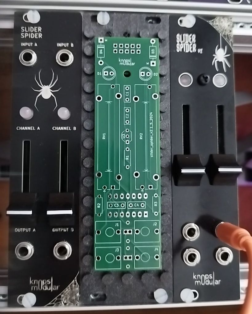
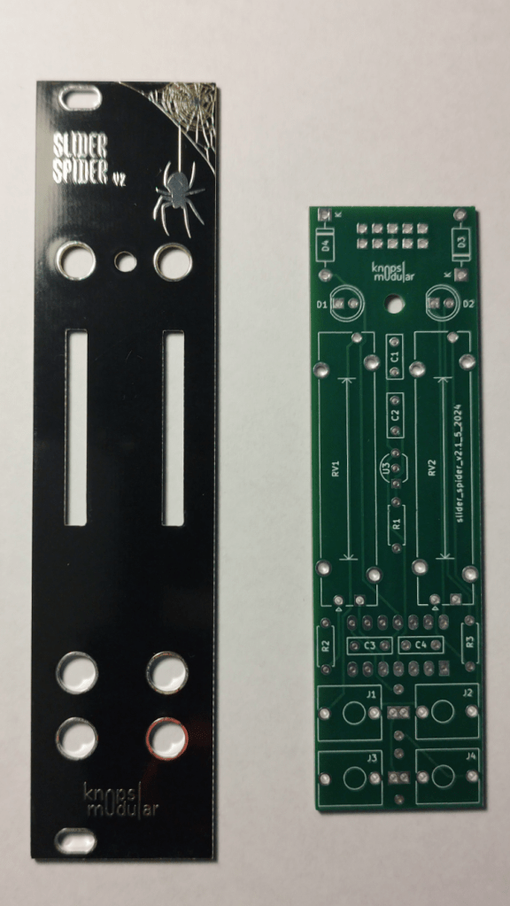
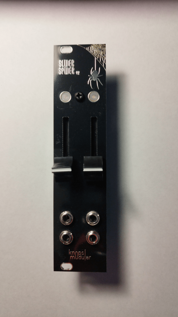
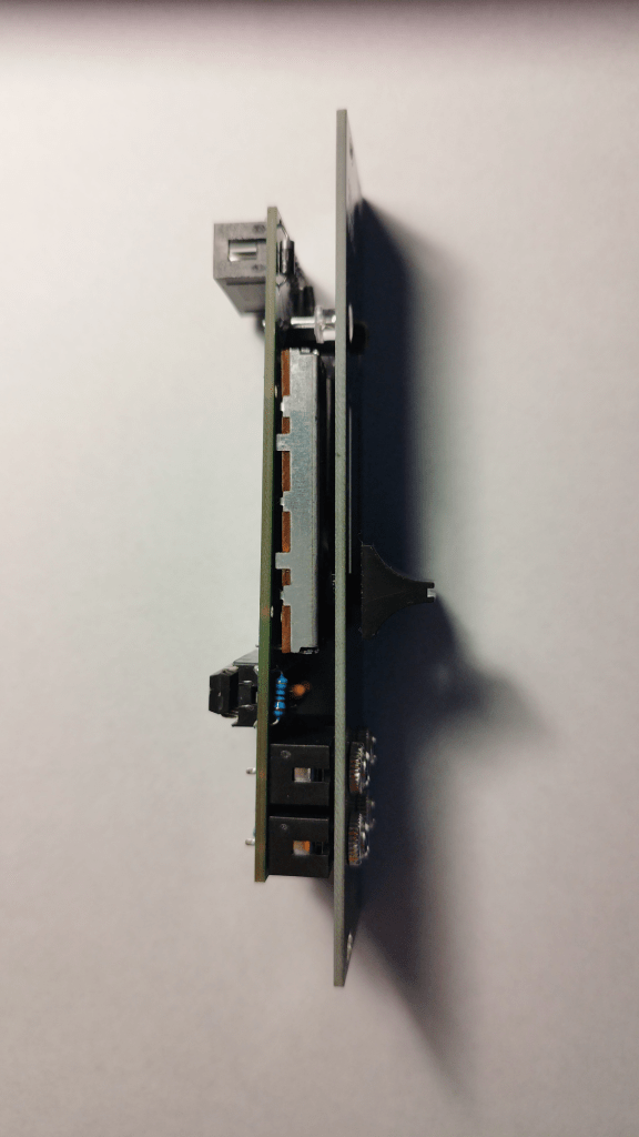
The slider spider v2 is a fancy dual attenuator, you can input (top jacksockets) a signal and attenuate it. The led indicators show how much of the signal comes through at the output (bottom jacksockets). Left and right got their own signal paths. Useable for audio and CV alike.
If there is no input you get a steady 5 V max output. So it doubles as a voltage source.
Flaws of the old design
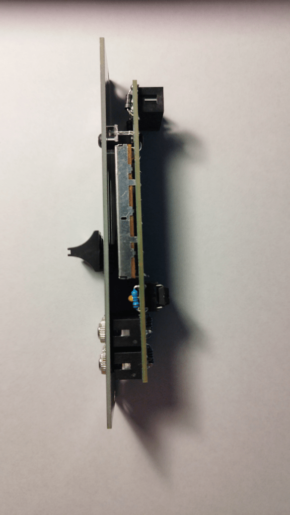
So first of all the build wasn’t too enjoyable in version 1 because I had the IDC header and a couple of components under the slide pots which is bad practice and brings its own electric problems. I’ve got overcome those with snipping them very close to the PCB and putting some electrical tape in-between components but it was no fun and after building a couple I was sure there is a better way.
The other thing was I wanted the jacksockets at the bottom and the led indicators were not showing any signal up to ~2.7V because I didn’t account for the LEDs voltage drop.
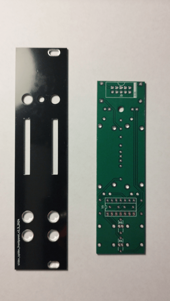
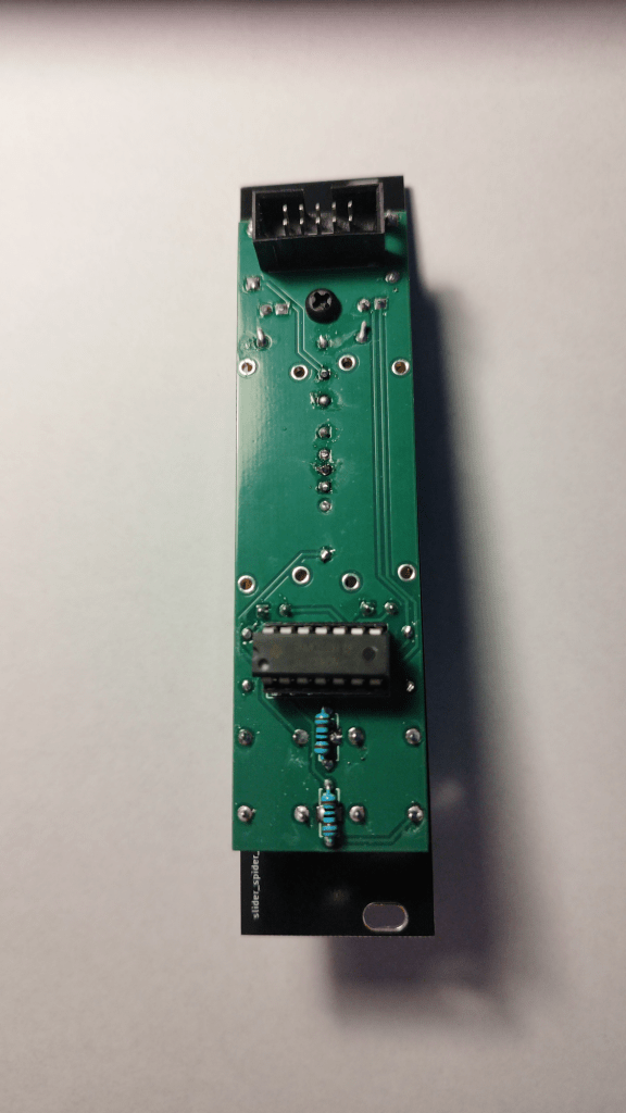
I fixed all of that in the new design by redoing the layout and changing the LED driver circuit from a transistor to an opamp circuit. Now I’m 90% happy with it. If I’ll revisit the design in the future idk but for now I think I’m good 😊

All of that was possible because of my kind sponsor PCBWAY
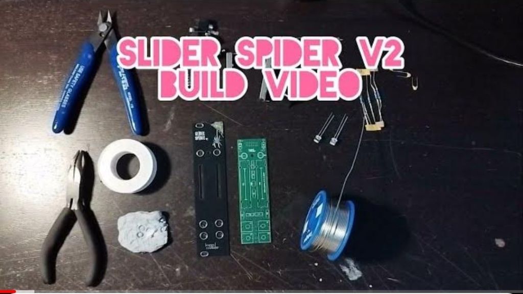
Videos
I made two YouTube videos for this module.

I hope you enjoyed this introduction to my new module. Please leave a like and subscribe to my videos if you did and find me on Instagram vía my Linktree 🤘
