
The Scope-o-Matic is a simple build that helps a lot with visualisation. I am in love. I like LEDs as indicators but this makes it so much easier to shape sounds.
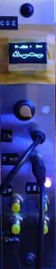
It has an input and I added a thru socket (mult) . The buttons on the left are up and down and right selext and hold. You got different parameters, you can change the voltage range, time, trigger and visual offset.
/*
PMO-RP1 V2.0
20200427_OLEDoscilloscope_V200E.ino)
sketch:23020byte、local variable:1231byte free
Apr.27 2020 by radiopench http://radiopench.blog96.fc2.com/
PMO-RP/JSB V2.0s
July 2020, simplified version by Zaphod B.
This version is meant to display the signal only for visual inspection of
the signal form, not for measurement purposes. Consequently this version:
- has no y-axis annotations,
- does not show the duty cycle,
- has no ticks on the x-axis,
- uses the full width of the display to show the signal.
PMO-RP/JSB V2.1
April 14. 2021,
- added vertical offset levelling menu item.
- Led will signal when data has been saved to EEPROM via pulsed flashing.
PMO-RP/JSB V2.2
May 7. 2021,
- storing vertical offset for each range to EEPROM
- voltage range menu now wraps around
*/
#include <Wire.h>
#include <Adafruit_GFX.h>
#include <Adafruit_SSD1306.h>
#include <EEPROM.h>
// Note: if you define SIMPLIFIED, then the code
// will show a simplified version of the original content.
// This is meant to display the signal only for visual inspection of
// its form, not for measurement purposes.
// If you do not define SIMPLIFIED, the display will show the content as
// show by the original v2.0 code by radiopench.
#define SIMPLIFIED
//#define SHOW_OFFSET
#ifdef SIMPLIFIED
#define BEGIN_X 0 // Begin position of plot on x-axis
//#define DISPLAY_ZERO_LINE 1
// #define FREQ_Y 0
// #define DISPLAY_FREQUENCY 1
#else
#define BEGIN_X 24 // Begin position of plot on x-axis
#define DISPLAY_AVERAGE_TR 1
#define DISPLAY_ZERO_LINE 1
#define DISPLAY_VERTICAL_MARKS 1
#define DISPLAY_VERTICAL_LINES 1
#define DISPLAY_VERTICAL_LINE_LEFT 1
#define DISPLAY_AVERAGE_TR 1
#define DISPLAY_AVERAGE_TL 1
#define DISPLAY_CENTER_VALUE 1
#define DISPLAY_DUTY_CYCLE 1
#define DISPLAY_FREQUENCY 1
#define FREQ_Y 12
// vertical position of plotted frequency in pixels
#endif
#define SCOPE_P_UPPER 3 // 4 menu items
#define FREQ_X 91
// horizontal position of plotted frequency in pixels
#define SCREEN_WIDTH 128 // OLED display width
#define SCREEN_HEIGHT 64 // OLED display height
#define REC_LENG 200 // size of wave data buffer
#define MIN_TRIG_SWING 5 // minimum trigger swing.(Display "Unsync" if swing smaller than this value
// Declaration for an SSD1306 display connected to I2C (SDA, SCL pins)
#define OLED_RESET -1 // Reset pin # (or -1 if sharing Arduino reset pin)
Adafruit_SSD1306 oled(SCREEN_WIDTH, SCREEN_HEIGHT, &Wire, OLED_RESET); // device name is oled
// Range name table (those are stored in flash memory)
#define VRANGE_MAX 10
const char vRangeName[10][5] PROGMEM = {"A50V", "A 5V", " 50V", " 20V", " 10V", " 5V", " 2V", " 1V", "0.5V", "0.2V"}; // Vertical display character (number of characters including \ 0 is required)
const char * const vstring_table[] PROGMEM = {vRangeName[0], vRangeName[1], vRangeName[2], vRangeName[3], vRangeName[4], vRangeName[5], vRangeName[6], vRangeName[7], vRangeName[8], vRangeName[9]};
const char hRangeName[10][6] PROGMEM = {"200ms", "100ms", " 50ms", " 20ms", " 10ms", " 5ms", " 2ms", " 1ms", "500us", "200us"}; // Hrizontal display characters
const char * const hstring_table[] PROGMEM = {hRangeName[0], hRangeName[1], hRangeName[2], hRangeName[3], hRangeName[4], hRangeName[5], hRangeName[6], hRangeName[7], hRangeName[8], hRangeName[9]};
const PROGMEM float hRangeValue[] = { 0.2, 0.1, 0.05, 0.02, 0.01, 0.005, 0.002, 0.001, 0.5e-3, 0.2e-3}; // horizontal range value in second. ( = 25pix on screen)
int dataOffset[VRANGE_MAX]; // Vertical offset for wave form.
int waveBuff[REC_LENG]; // Wave form buffer (RAM remaining capacity is barely)
char chrBuff[8]; // Display string buffer
char hScale[] = "xxxAs"; // Horizontal scale character
char vScale[] = "xxxx"; // Vertical scale
float lsb5V = 0.00566826; // Sensivity coefficient of 5V range. std=0.00563965 1.1*630/(1024*120)
float lsb50V = 0.05243212; // Sensivity coefficient of 50V range. std=0.0512898 1.1*520.91/(1024*10.91)
volatile int vRange; // V-range number 0:A50V, 1:A 5V, 2:50V, 3:20V, 4:10V, 5:5V, 6:2V, 7:1V, 8:0.5V, 9:0.2V
volatile int hRange; // H-range number 0:200ms, 1:100ms, 2:50ms, 3:20ms, 4:10ms, 5:5ms, 6;2ms, 7:1ms, 8:500us, 9;200us
volatile int trigD; // trigger slope flag, 0:positive 1:negative
volatile int scopeP; // Operation scope position number. 0:Vertical, 1:Horizontal, 2:Trigger slope
volatile boolean hold = false; // Hold flag
volatile boolean switchPushed = false; // flag of switch pushed !
volatile int saveTimer; // Remaining time for saving EEPROM
int timeExec; // Approx. execution time of current range setting (ms)
int dataMin; // Buffer minimum value (smallest=0)
int dataMax; // maximum value (largest=1023)
int dataAve; // 10 x average value (use 10x value to keep accuracy. so, max=10230)
int rangeMax; // Buffer value to graph full swing
int rangeMin; // Buffer value of graph botto
int rangeMaxDisp; // Display value of max. (100x value)
int rangeMinDisp; // Display value if min.
int trigP; // Trigger position pointer on data buffer
boolean trigSync; // Flag of trigger detected
int att10x; // 10x attenuator ON (effective when 1)
float waveFreq; // Frequency (Hz)
float waveDuty; // Duty ratio (%)
template <class T> int EEPROM_writeAnything(int ee, const T& value)
{
const byte* p = (const byte*)(const void*)&value;
unsigned int i;
for (i = 0; i < sizeof(value); i++)
EEPROM.write(ee++, *p++);
return i;
}
template <class T> int EEPROM_readAnything(int ee, T& value)
{
byte* p = (byte*)(void*)&value;
unsigned int i;
for (i = 0; i < sizeof(value); i++)
*p++ = EEPROM.read(ee++);
return i;
}
void setup() {
pinMode( 2, INPUT_PULLUP); // Button pussed interrupt (int.0 IRQ)
pinMode( 8, INPUT_PULLUP); // Select button
pinMode( 9, INPUT_PULLUP); // Down
pinMode(10, INPUT_PULLUP); // Up
pinMode(11, INPUT_PULLUP); // Hold
pinMode(12, INPUT); // 1/10 attenuator(Off=High-Z, Enable=Output Low)
pinMode(13, OUTPUT); // LED
//Serial.begin(115200); // A lot of RAM is used when activating this. (may by crash!)
if (!oled.begin(SSD1306_SWITCHCAPVCC, 0x3C)) { // select 3C or 3D (set your OLED I2C address)
for (;;); // loop forever
}
auxFunctions(); // Voltage measure (never return)
loadEEPROM(); // Read last settings from EEPROM
analogReference(INTERNAL); // ADC full scale = 1.1V
attachInterrupt(0, pin2IRQ, FALLING); // Activate IRQ at falling edge mode
startScreen(); // Display start message
}
void loop() {
setConditions(); // Set measurement conditions
digitalWrite(13, HIGH); // Flash LED at start of measurement.
readWave(); // Read wave form and store into buffer memory.
digitalWrite(13, LOW); // Stop LED at end of measurement.
setConditions(); // Set measurment conditions again (reflect change during measure).
dataAnalyze(); // Analyze data.
writeCommonImage(); // Write fixed screen image (2.6ms).
plotData(); // Plot waveform (10-18ms).
dispInf(); // Display information (6.5-8.5ms).
oled.display(); // Send screen buffer to OLED (37ms).
saveEEPROM(); // Save settings to EEPROM if necessary.
while (hold == true) { // Wait if Hold flag ON.
dispHold();
delay(10);
} // Loop cycle speed = 60-470ms (buffer size = 200)
}
void setConditions() { // measuring condition setting
// get range name from PROGMEM
strcpy_P(hScale, (char*)pgm_read_word(&(hstring_table[hRange]))); // H range name
strcpy_P(vScale, (char*)pgm_read_word(&(vstring_table[vRange]))); // V range name
switch (vRange) { // setting of Vrange
case 0: { // Auto50V range
att10x = 1; // use input attenuator
break;
}
case 1: { // Auto 5V range
att10x = 0; // no attenuator
break;
}
case 2: { // 50V range
rangeMax = 50 / lsb50V; // Set full scale pixcel count number
rangeMaxDisp = 5000; // Vertical scale (set100x value)
rangeMin = 0;
rangeMinDisp = 0;
att10x = 1; // Use input attenuator
break;
}
case 3: { // 20V range
rangeMax = 20 / lsb50V; // Set full scale pixcel count number
rangeMaxDisp = 2000;
rangeMin = 0;
rangeMinDisp = 0;
att10x = 1; // Use input attenuator
break;
}
case 4: { // 10V range
rangeMax = 10 / lsb50V; // Set full scale pixcel count number
rangeMaxDisp = 1000;
rangeMin = 0;
rangeMinDisp = 0;
att10x = 1; // Use input attenuator
break;
}
case 5: { // 5V range
rangeMax = 5 / lsb5V; // Set full scale pixcel count number
rangeMaxDisp = 500;
rangeMin = 0;
rangeMinDisp = 0;
att10x = 0; // No input attenuator
break;
}
case 6: { // 2V range
rangeMax = 2 / lsb5V; // Set full scale pixcel count number
rangeMaxDisp = 200;
rangeMin = 0;
rangeMinDisp = 0;
att10x = 0; // No input attenuator
break;
}
case 7: { // 1V range
rangeMax = 1 / lsb5V; // Set full scale pixcel count number
rangeMaxDisp = 100;
rangeMin = 0;
rangeMinDisp = 0;
att10x = 0; // No input attenuator
break;
}
case 8: { // 0.5V range
rangeMax = 0.5 / lsb5V; // Set full scale pixcel count number
rangeMaxDisp = 50;
rangeMin = 0;
rangeMinDisp = 0;
att10x = 0; // No input attenuator
break;
}
case 9: { // 0.5V range
rangeMax = 0.2 / lsb5V; // set full scale pixcel count number
rangeMaxDisp = 20;
rangeMin = 0;
rangeMinDisp = 0;
att10x = 0; // No input attenuator
break;
}
}
}
void writeCommonImage() { // Show menu.
oled.clearDisplay(); // Erase all(0.4ms)
oled.setTextColor(WHITE); // Use white characters (in case of multi color display).
#ifdef DISPLAY_AVERAGE_TR
oled.setCursor(86, 0); // Start at top-left corner
oled.println(F("av V")); // 1-st line fixed characters
#endif
#ifdef DISPLAY_VERTICAL_LINE_LEFT
oled.drawFastVLine(BEGIN_X + 2, 9, 55, WHITE); // left vertical line
#endif
#ifdef DISPLAY_VERTICAL_MARKS
oled.drawFastVLine(SCREEN_WIDTH - 1, 9, 3, WHITE); // right vertical line up
oled.drawFastVLine(SCREEN_WIDTH - 1, 61, 3, WHITE);// right vertical line bottom
oled.drawFastHLine(BEGIN_X, 9, 7, WHITE); // Max value auxiliary mark
oled.drawFastHLine(BEGIN_X, 36, 2, WHITE);
oled.drawFastHLine(BEGIN_X, 63, 7, WHITE);
oled.drawFastHLine(BEGIN_X + 27, 9, 3, WHITE); // Max value auxiliary mark.
oled.drawFastHLine(BEGIN_X + 27, 63, 3, WHITE);
oled.drawFastHLine(BEGIN_X + 52, 9, 3, WHITE); // Max value auxiliary mark.
oled.drawFastHLine(BEGIN_X + 52, 63, 3, WHITE);
oled.drawFastHLine(BEGIN_X + 77, 9, 3, WHITE); // Max value auxiliary mark.
oled.drawFastHLine(BEGIN_X + 77, 63, 3, WHITE);
oled.drawFastHLine(BEGIN_X + 99, 9, 5, WHITE); // Right side Max value auxiliary mark.
oled.drawFastHLine(BEGIN_X + 99, 63, 5, WHITE);
#endif
#ifdef DISPLAY_ZERO_LINE
// for (int x = BEGIN_X + 2; x <= SCREEN_WIDTH; x += 5) {
// There are 100 samples that are displayed.
// So we need a zero line of that same length.
#ifdef SIMPLIFIED
for (int x = BEGIN_X + 2; x <= SCREEN_WIDTH - 1 + BEGIN_X + 2; x += 5) {
oled.drawFastHLine(x, 36, 2, WHITE); // Draw the center line (horizontal line) with a dotted line.
}
#else
for (int x = BEGIN_X + 2; x <= 100 + BEGIN_X + 2; x += 5) {
oled.drawFastHLine(x, 36, 2, WHITE); // Draw the center line (horizontal line) with a dotted line.
}
#endif
#endif
#ifdef DISPLAY_VERTICAL_LINES
for (int x = (SCREEN_WIDTH - 1 - 25); x > 6; x -= 25) {
for (int y = 10; y < 63; y += 5) {
oled.drawFastVLine(x, y, 2, WHITE); // Draw 3 vertical lines with dotted lines.
}
}
#endif
}
void readWave() { // Record waveform to memory array
if (att10x == 1) { // If 1/10 attenuator required
pinMode(12, OUTPUT); // assign attenuator controle pin to OUTPUT,
digitalWrite(12, LOW); // and output LOW (output 0V)
} else { // If not required
pinMode(12, INPUT); // assign the pin input (Hi-z).
}
switchPushed = false; // Clear switch operation flag
switch (hRange) { // Set recording conditions in accordance with the range number
case 0: { // 200ms range.
timeExec = 1600 + 60; // Approximate execution time(ms) Used for countdown until saving to EEPROM.
ADCSRA = ADCSRA & 0xf8; // Clear bottom 3bit.
ADCSRA = ADCSRA | 0x07; // dividing ratio = 128 (default of Arduino)
for (int i = 0; i < REC_LENG; i++) { // Up to rec buffer size
waveBuff[i] = analogRead(0); // read and save approx 112us
delayMicroseconds(7888); // timing adjustment
if (switchPushed == true) { // If any switch touched then
switchPushed = false;
break; // abandon record (this improves response time).
}
}
break;
}
case 1: { // 100ms range
timeExec = 800 + 60; // Approximate execution time(ms) Used for countdown until saving to EEPROM
ADCSRA = ADCSRA & 0xf8; // clear bottom 3bit
ADCSRA = ADCSRA | 0x07; // dividing ratio = 128 (default of Arduino)
for (int i = 0; i < REC_LENG; i++) { // up to rec buffer size
waveBuff[i] = analogRead(0); // read and save approx 112us
// delayMicroseconds(3888); // timing adjustment
delayMicroseconds(3860); // timing adjustment tuned
if (switchPushed == true) { // if any switch touched
switchPushed = false;
break; // abandon record(this improve response)
}
}
break;
}
case 2: { // 50ms range
timeExec = 400 + 60; // Approximate execution time(ms)
ADCSRA = ADCSRA & 0xf8; // clear bottom 3bit
ADCSRA = ADCSRA | 0x07; // dividing ratio = 128 (default of Arduino)
for (int i = 0; i < REC_LENG; i++) { // up to rec buffer size
waveBuff[i] = analogRead(0); // read and save approx 112us
// delayMicroseconds(1888); // timing adjustment
delayMicroseconds(1880); // timing adjustment tuned
if (switchPushed == true) { // if any switch touched
break; // abandon record(this improve response)
}
}
break;
}
case 3: { // 20ms range
timeExec = 160 + 60; // Approximate execution time(ms)
ADCSRA = ADCSRA & 0xf8; // clear bottom 3bit
ADCSRA = ADCSRA | 0x07; // dividing ratio = 128 (default of Arduino)
for (int i = 0; i < REC_LENG; i++) { // up to rec buffer size
waveBuff[i] = analogRead(0); // read and save approx 112us
// delayMicroseconds(688); // timing adjustment
delayMicroseconds(686); // timing adjustment tuned
if (switchPushed == true) { // if any switch touched
break; // abandon record(this improve response)
}
}
break;
}
case 4: { // 10ms range
timeExec = 80 + 60; // Approximate execution time(ms)
ADCSRA = ADCSRA & 0xf8; // clear bottom 3bit
ADCSRA = ADCSRA | 0x07; // dividing ratio = 128 (default of Arduino)
for (int i = 0; i < REC_LENG; i++) { // up to rec buffer size
waveBuff[i] = analogRead(0); // read and save approx 112us
// delayMicroseconds(288); // timing adjustment
delayMicroseconds(287); // timing adjustment tuned
if (switchPushed == true) { // if any switch touched
break; // abandon record(this improve response)
}
}
break;
}
case 5: { // 5ms range
timeExec = 40 + 60; // Approximate execution time(ms)
ADCSRA = ADCSRA & 0xf8; // clear bottom 3bit
ADCSRA = ADCSRA | 0x07; // dividing ratio = 128 (default of Arduino)
for (int i = 0; i < REC_LENG; i++) { // up to rec buffer size
waveBuff[i] = analogRead(0); // read and save approx 112μs
// delayMicroseconds(88); // timing adjustment
delayMicroseconds(87); // timing adjustment tuned
if (switchPushed == true) { // if any switch touched
break; // abandon record(this improve response)
}
}
break;
}
case 6: { // 2ms range
timeExec = 16 + 60; // Approximate execution time(ms)
ADCSRA = ADCSRA & 0xf8; // clear bottom 3bit
ADCSRA = ADCSRA | 0x06; // dividing ratio = 64 (0x1=2, 0x2=4, 0x3=8, 0x4=16, 0x5=32, 0x6=64, 0x7=128)
for (int i = 0; i < REC_LENG; i++) { // up to rec buffer size
waveBuff[i] = analogRead(0); // read and save approx 56us
// delayMicroseconds(24); // timing adjustment
delayMicroseconds(23); // timing adjustment tuned
}
break;
}
case 7: { // 1ms range
timeExec = 8 + 60; // Approximate execution time(ms)
ADCSRA = ADCSRA & 0xf8; // clear bottom 3bit
ADCSRA = ADCSRA | 0x05; // dividing ratio = 16 (0x1=2, 0x2=4, 0x3=8, 0x4=16, 0x5=32, 0x6=64, 0x7=128)
for (int i = 0; i < REC_LENG; i++) { // up to rec buffer size
waveBuff[i] = analogRead(0); // read and save approx 28us
// delayMicroseconds(12); // timing adjustment
delayMicroseconds(10); // timing adjustment tuned
}
break;
}
case 8: { // 500us range
timeExec = 4 + 60; // Approximate execution time(ms)
ADCSRA = ADCSRA & 0xf8; // clear bottom 3bit
ADCSRA = ADCSRA | 0x04; // dividing ratio = 16(0x1=2, 0x2=4, 0x3=8, 0x4=16, 0x5=32, 0x6=64, 0x7=128)
for (int i = 0; i < REC_LENG; i++) { // up to rec buffer size
waveBuff[i] = analogRead(0); // read and save approx 16us
delayMicroseconds(4); // timing adjustment
// time fine adjustment 0.0625 x 8 = 0.5us(nop=0.0625us @16MHz)
asm("nop"); asm("nop"); asm("nop"); asm("nop"); asm("nop"); asm("nop"); asm("nop"); asm("nop");
}
break;
}
case 9: { // 200us range
timeExec = 2 + 60; // Approximate execution time(ms)
ADCSRA = ADCSRA & 0xf8; // clear bottom 3bit
ADCSRA = ADCSRA | 0x02; // dividing ratio = 4(0x1=2, 0x2=4, 0x3=8, 0x4=16, 0x5=32, 0x6=64, 0x7=128)
for (int i = 0; i < REC_LENG; i++) { // up to rec buffer size
waveBuff[i] = analogRead(0); // read and save approx 6us
// time fine adjustment 0.0625 * 20 = 1.25us (nop=0.0625us @16MHz)
asm("nop"); asm("nop"); asm("nop"); asm("nop"); asm("nop"); asm("nop"); asm("nop"); asm("nop"); asm("nop"); asm("nop");
asm("nop"); asm("nop"); asm("nop"); asm("nop"); asm("nop"); asm("nop"); asm("nop"); asm("nop"); asm("nop"); asm("nop");
}
break;
}
}
}
void dataAnalyze() { // get various information from wave form
int d;
long sum = 0;
// search max and min value
dataMin = 1023; // min value initialize to big number
dataMax = 0; // max value initialize to small number
for (int i = 0; i < REC_LENG; i++) { // serach max min value
d = waveBuff[i];
sum = sum + d;
if (d < dataMin) { // update min
dataMin = d;
}
if (d > dataMax) { // updata max
dataMax = d;
}
}
// calculate average
dataAve = (sum + 10) / 20; // Average value calculation (calculated by 10 times to improve accuracy)
// Decide display's max min value
if (vRange <= 1) { // if Autorange(Range number <= 1)
rangeMin = dataMin - 20; // maintain bottom margin 20
rangeMin = (rangeMin / 10) * 10; // round 10
if (rangeMin < 0) {
rangeMin = 0; // no smaller than 0
}
rangeMax = dataMax + 20; // Set display top at data max +20
rangeMax = ((rangeMax / 10) + 1) * 10; // Round up 10
if (rangeMax > 1020) {
rangeMax = 1023; // If more than 1020, hold down at 1023
}
if (att10x == 1) { // if 10x attenuator used
rangeMaxDisp = 100 * (rangeMax * lsb50V); // display range is determined by the data.(the upper limit is up to the full scale of the ADC)
rangeMinDisp = 100 * (rangeMin * lsb50V); // lower depend on data, but zero or more
} else { // if no attenuator used
rangeMaxDisp = 100 * (rangeMax * lsb5V);
rangeMinDisp = 100 * (rangeMin * lsb5V);
}
} else { // if fix range
// Write necessary code here (none for now)
}
// Trigger position search
for (trigP = ((REC_LENG / 2) - 51); trigP < ((REC_LENG / 2) + 50); trigP++) {
// Find the points that straddle the median at the center ± 50 of the data range
if (trigD == 0) { // if trigger direction is positive
if ((waveBuff[trigP - 1] < (dataMax + dataMin) / 2) && (waveBuff[trigP] >= (dataMax + dataMin) / 2)) {
break; // Positive trigger position found!
}
} else { // Trigger direction is negative.
if ((waveBuff[trigP - 1] > (dataMax + dataMin) / 2) && (waveBuff[trigP] <= (dataMax + dataMin) / 2)) {
break;
} // Negative trigger position found!
}
}
trigSync = true;
if (trigP >= ((REC_LENG / 2) + 50)) { // If the trigger is not found in range
trigP = (REC_LENG / 2); // Set it to the center for the time being
trigSync = false; // Set Unsync display flag.
}
if ((dataMax - dataMin) <= MIN_TRIG_SWING) { // Amplitude of the waveform smaller than the specified value.
trigSync = false; // Set Unsync display flag.
}
freqDuty();
}
void freqDuty() { // Detect frequency and duty cycle value from waveform data
int swingCenter; // Center of wave (half of p-p)
float p0 = 0; // 1-st posi edge
float p1 = 0; // Total length of cycles
float p2 = 0; // Total length of pulse high time
float pFine = 0; // Fine position (0-1.0)
float lastPosiEdge; // Last positive edge position
float pPeriod; // Pulse period
float pWidth; // Pulse width
int p1Count = 0; // Wave cycle count
int p2Count = 0; // High time count
boolean a0Detected = false;
boolean posiSearch = true; // True when searching posi edge
swingCenter = (3 * (dataMin + dataMax)) / 2; // Calculate wave center value
for (int i = 1; i < REC_LENG - 2; i++) { // Scan all over the buffer
if (posiSearch == true) { // Positive slope (frequency search)
if ((sum3(i) <= swingCenter) && (sum3(i + 1) > swingCenter)) { // if across the center when rising (+-3data used to eliminate noize)
pFine = (float)(swingCenter - sum3(i)) / ((swingCenter - sum3(i)) + (sum3(i + 1) - swingCenter) ); // fine cross point calc.
if (a0Detected == false) { // If 1-st cross
a0Detected = true; // Set find flag
p0 = i + pFine; // Save this position as startposition
} else {
p1 = i + pFine - p0; // Record length (length of n*cycle time)
p1Count++;
}
lastPosiEdge = i + pFine; // Record location for Pw calcration
posiSearch = false;
}
} else { // Negative slope search (duration saerch)
if ((sum3(i) >= swingCenter) && (sum3(i + 1) < swingCenter)) { // if across the center when falling (+-3data used to eliminate noize)
pFine = (float)(sum3(i) - swingCenter) / ((sum3(i) - swingCenter) + (swingCenter - sum3(i + 1)) );
if (a0Detected == true) {
p2 = p2 + (i + pFine - lastPosiEdge); // calculate pulse width and accumurate it
p2Count++;
}
posiSearch = true;
}
}
}
pPeriod = p1 / p1Count; // pulse period
pWidth = p2 / p2Count; // palse width
waveFreq = 1.0 / ((pgm_read_float(hRangeValue + hRange) * pPeriod) / 25.0); // frequency
waveDuty = 100.0 * pWidth / pPeriod; // duty ratio
}
int sum3(int k) { // Sum of before and after and own value
int m = waveBuff[k - 1] + waveBuff[k] + waveBuff[k + 1];
return m;
}
void startScreen() { // Start up screen
oled.clearDisplay();
oled.setTextSize(2); // at double size character
oled.setTextColor(WHITE);
oled.setCursor(4, 15);
oled.println(F("PMO-RP/JSB")); // Title(Poor Man's Osilloscope, RadioPench 1)
#ifdef SIMPLIFIED
oled.setCursor(9, 35);
oled.println(F(" v2.2s")); // simplified version No.
#else
oled.setCursor(10, 35);
oled.println(F(" v2.0")) ; // 'original' version No.
#endif
oled.display(); // Actual display here.
delay(1500);
oled.clearDisplay();
oled.setTextSize(1); // After this, standard font size.
}
void dispHold() { // Display "Hold".
oled.fillRect(42, 11, 24, 8, BLACK); // Black paint 4 characters.
oled.setCursor(42, 11);
oled.print(F("Hold")); // Hold
oled.display(); //
}
void dispInf() { // Display of various information
float voltage;
// Display vertical sensitivity.
oled.setCursor(2, 0); // Around top left
oled.print(vScale); // Vertical sensitivity value
if (scopeP == 0) { // if scoped then
oled.drawFastHLine(0, 7, 27, WHITE); // display scoped mark at the bottom.
oled.drawFastVLine(0, 5, 2, WHITE);
oled.drawFastVLine(26, 5, 2, WHITE);
}
// Display horizontal sweep speed.
oled.setCursor(34, 0); //
oled.print(hScale); // Display sweep speed (time/div).
if (scopeP == 1) { // If scoped then
oled.drawFastHLine(32, 7, 33, WHITE); // display scoped mark at the bottom.
oled.drawFastVLine(32, 5, 2, WHITE);
oled.drawFastVLine(64, 5, 2, WHITE);
}
// SHow trigger polarity.
oled.setCursor(75, 0); // At top center
if (trigD == 0) { // if positive then
oled.print(char(0x18)); // show up mark,
} else {
oled.print(char(0x19)); // else show down mark.
}
if (scopeP == 2) { // If scoped then
oled.drawFastHLine(71, 7, 13, WHITE); // display scoped mark at the bottom.
oled.drawFastVLine(71, 5, 2, WHITE);
oled.drawFastVLine(83, 5, 2, WHITE);
}
// Show calibration menu item.
oled.setCursor(100, 0); // Top right
#ifndef SHOW_OFFSET
oled.print("Zero");
#else
oled.print(dataOffset[vRange]);
#endif
if (scopeP == 3) {
oled.drawFastHLine( 98, 7, 28, WHITE); // Display zero menu item mark.
oled.drawFastVLine( 98, 5, 2, WHITE);
oled.drawFastVLine(125, 5, 2, WHITE);
}
#ifdef DISPLAY_AVERAGE_TR
// Average voltage top right
if (att10x == 1) { // if 10x attenuator is used
voltage = dataAve * lsb50V / 10.0; // 50V range value
} else { // no!
voltage = dataAve * lsb5V / 10.0; // 5V range value
}
if (voltage < 10.0) { // if less than 10V
dtostrf(voltage, 4, 2, chrBuff); // format x.xx
} else { // no!
dtostrf(voltage, 4, 1, chrBuff); // format xx.x
}
oled.setCursor(98, 0); // around the top right
oled.print(chrBuff); // display average voltage
// oled.print(saveTimer); // use here for debugging
#endif
#ifdef DISPLAY_AVERAGE_TL
// average voltage top left
// vertical scale lines
voltage = rangeMaxDisp / 100.0; // convert Max voltage
if (vRange == 1 || vRange > 4) { // if range below 5V or Auto 5V
dtostrf(voltage, 4, 2, chrBuff); // format *.**
} else { // no!
dtostrf(voltage, 4, 1, chrBuff); // format **.*
}
oled.setCursor(0, 9);
oled.print(chrBuff); // display Max value
#endif
#ifdef DISPLAY_CENTER_VALUE
voltage = (rangeMaxDisp + rangeMinDisp) / 200.0; // center value calculation
if (vRange == 1 || vRange > 4) { // if range below 5V or Auto 5V
dtostrf(voltage, 4, 2, chrBuff); // format *.**
} else { // no!
dtostrf(voltage, 4, 1, chrBuff); // format **.*
}
oled.setCursor(0, 33);
oled.print(chrBuff); // display the value
#endif
#ifdef DISPLAY_MIN
// Bottom left
voltage = rangeMinDisp / 100.0; // convert Min voltage
if (vRange == 1 || vRange > 4) { // if range below 5V or Auto 5V
dtostrf(voltage, 4, 2, chrBuff); // format *.**
} else { // no!
dtostrf(voltage, 4, 1, chrBuff); // format **.*
}
oled.setCursor(0, 57);
oled.print(chrBuff); // display the value
#endif
// Display frequency, duty % or trigger missed.
#ifdef DISPLAY_FREQUENCY
if (trigSync == false) { // If trigger point can't found
oled.fillRect(FREQ_X + 1, FREQ_Y + 2, 24, 8, BLACK); // black paint 4 character
oled.setCursor(FREQ_X + 1, FREQ_Y + 2); //
oled.print(F("unSync")); // display Unsync
} else {
oled.fillRect(FREQ_X, FREQ_Y, 25, 9, BLACK); // erase Freq area
oled.setCursor(FREQ_X + 1, FREQ_Y + 1); // set display locatio
if (waveFreq < 100.0) { // if less than 100Hz
oled.print(waveFreq, 1); // display 99.9Hz
oled.print(F("Hz"));
} else if (waveFreq < 1000.0) { // if less than 1000Hz
oled.print(waveFreq, 0); // display 999Hz
oled.print(F("Hz"));
} else if (waveFreq < 10000.0) { // if less than 10kHz
oled.print((waveFreq / 1000.0), 2); // display 9.99kH
oled.print(F("kH"));
} else { // if more
oled.print((waveFreq / 1000.0), 1); // display 99.9kH
oled.print(F("kH"));
}
#ifdef DISPLAY_DUTY_CYCLE
oled.fillRect(FREQ_X + 6, FREQ_Y + 9, 25, 10, BLACK); // Erase Freq area (as small as possible).
oled.setCursor(FREQ_X + 7, FREQ_Y + 11); // Set location.
oled.print(waveDuty, 1); // Sisplay duty (High level ratio) in %.
oled.print(F("%"));
#endif
}
#endif
}
#ifdef SIMPLIFIED
void plotData() { // Plot wave form on OLED over full screen width.
long y1, y2;
for (int x = 0; x <= 98; x++) {
y1 = map(waveBuff[x + trigP - 50] + dataOffset[vRange], rangeMin, rangeMax, 63, 9); // Convert to plot address
y1 = constrain(y1, 9, 63); // Crush(Saturate) the protruding part
y2 = map(waveBuff[x + trigP - 49] + dataOffset[vRange], rangeMin, rangeMax, 63, 9); // Convert to plot address
y2 = constrain(y2, 9, 63); // Limit y2 to the range [9...63]
int xx = map(x, 0, 98, 0, SCREEN_WIDTH - 1);
oled.drawLine(xx + BEGIN_X + 3, y1, xx + BEGIN_X + 4, y2, WHITE);// connect between point
}
}
#else
void plotData() { // Plot wave form on OLED over part of screen.
long y1, y2;
for (int x = 0; x <= 98; x++) {
y1 = map(waveBuff[x + trigP - 50], rangeMin, rangeMax, 63, 9); // Convert to plot address
y1 = constrain(y1, 9, 63); // Crush(Saturate) the protruding part
y2 = map(waveBuff[x + trigP - 49], rangeMin, rangeMax, 63, 9);
y2 = constrain(y2, 9, 63);
oled.drawLine(x + BEGIN_X + 3, y1, x + BEGIN_X + 4, y2, WHITE);// Connect between point
}
}
#endif
void flashLed() {
for (int j = 0; j < 3; j++){
for (int i = 0; i < 5; i++){
digitalWrite(13, HIGH); // LED on.
delay(100);
digitalWrite(13, LOW); // LED off.
delay(10);
}
delay(300);
}
}
void saveEEPROM() { // Save the setting value in EEPROM after waiting a while after the button operation.
if (saveTimer > 0) { // If the timer value is positive,
saveTimer = saveTimer - timeExec; // Timer subtraction
if (saveTimer < 0) { // if time up
EEPROM.write(0, vRange); // save current status to EEPROM
EEPROM.write(1, hRange);
EEPROM.write(2, trigD);
EEPROM.write(3, scopeP);
for (int i = 0; i < VRANGE_MAX; i++) {
EEPROM_writeAnything(4 + i * sizeof(int), dataOffset[i]);
}
flashLed(); // Signal to user that data was written to EEPROM.
}
}
}
void loadEEPROM() { // Read setting values from EEPROM (abnormal values will be corrected to default)
vRange = EEPROM.read(0); // vRange
if ((vRange < 0) || (vRange > 9)) { // if out side 0-9
vRange = 3; // default value
}
hRange = EEPROM.read(1); // hRange
if ((hRange < 0) || (hRange > 9)) { // if out of 0-9
hRange = 3; // default value
}
trigD = EEPROM.read(2); // trigD
if ((trigD < 0) || (trigD > 1)) { // if out of 0-1
trigD = 1; // default value
}
scopeP = EEPROM.read(3); // scopeP
if ((scopeP < 0) || (scopeP > 3)) { // if out of 0-3
scopeP = 0; // default value
}
for (int i = 0; i < VRANGE_MAX; i++) {
EEPROM_readAnything(4 + i * sizeof(int), dataOffset[i]); // Data display offset value.
if ((dataOffset[i] < -800) || (dataOffset[i] > 250)) { // Default value is 0.
dataOffset[i] = 0;
}
}
}
void auxFunctions() { // voltage meter function
float voltage;
long x;
if (digitalRead(8) == LOW) { // if SELECT button pushed, measure battery voltage
analogReference(DEFAULT); // ADC full scale set to Vcc
while (1) { // do forever
x = 0;
for (int i = 0; i < 100; i++) { // 100 times
x = x + analogRead(1); // read A1 pin voltage and accumulate
}
voltage = (x / 100.0) * 5.0 / 1023.0; // convert voltage value
oled.clearDisplay(); // all erase screen(0.4ms)
oled.setTextColor(WHITE); // write in white character
oled.setCursor(20, 16); //
oled.setTextSize(1); // standerd size character
oled.println(F("Battery voltage"));
oled.setCursor(35, 30); //
oled.setTextSize(2); // double size character
dtostrf(voltage, 4, 2, chrBuff); // display batterry voltage x.xxV
oled.print(chrBuff);
oled.println(F("V"));
oled.display();
delay(150);
}
}
if (digitalRead(9) == LOW) { // if UP button pushed, 5V range
analogReference(INTERNAL); // Configures the reference voltage used for analog input
// (i.e. the value used as the top of the input range).
// INTERNAL: an built-in reference, equal to 1.1 volts on the
// ATmega168 or ATmega328 and 2.56 volts on the ATmega8 (not
// available on the Arduino Mega).
pinMode(12, INPUT); // Set the attenuator control pin to Hi-z (use as input)
while (1) { // do forever,
digitalWrite(13, HIGH); // flash LED
voltage = analogRead(0) * lsb5V; // measure voltage
oled.clearDisplay(); // erase screen (0.4ms)
oled.setTextColor(WHITE); // write in white character
oled.setCursor(26, 16); //
oled.setTextSize(1); // by standerd size character
oled.println(F("DVM 5V Range"));
oled.setCursor(35, 30); //
oled.setTextSize(2); // double size character
dtostrf(voltage, 4, 2, chrBuff); // display batterry voltage x.xxV
oled.print(chrBuff);
oled.println(F("V"));
oled.display();
digitalWrite(13, LOW); // stop LED flash
delay(150);
}
}
if (digitalRead(10) == LOW) { // if DOWN botton pushed, 50V range
analogReference(INTERNAL);
pinMode(12, OUTPUT); // Set the attenuator control pin to OUTPUT
digitalWrite(12, LOW); // output LOW
while (1) { // do forever
digitalWrite(13, HIGH); // flush LED
voltage = analogRead(0) * lsb50V; // measure voltage
oled.clearDisplay(); // erase screen (0.4ms)
oled.setTextColor(WHITE); // write in white character
oled.setCursor(26, 16); //
oled.setTextSize(1); // by standerd size character
oled.println(F("DVM 50V Range"));
oled.setCursor(35, 30); //
oled.setTextSize(2); // double size character
dtostrf(voltage, 4, 1, chrBuff); // display batterry voltage xx.xV
oled.print(chrBuff);
oled.println(F("V"));
oled.display();
digitalWrite(13, LOW); // stop LED flash
delay(150);
}
}
}
void pin2IRQ() { // Pin2(int.0) interrupt handler
// Pin8,9,10,11 buttons are bundled with diodes and connected to Pin2.
// So, if any button is pressed, this routine will start.
int x; // Port information holding variable
x = PINB; // read port B status
if ( (x & 0x07) != 0x07) { // if bottom 3bit is not all Hi (any were pressed)
saveTimer = 5000; // set EEPROM save timer to 5 second
switchPushed = true; // switch pushed falag ON
}
if ((x & 0x01) == 0) { // if select button(Pin8) pushed,
scopeP++; // forward scope position
if (scopeP > SCOPE_P_UPPER) { // if upper limit
scopeP = 0; // move to start position
}
}
if ((x & 0x02) == 0) { // if UP button pushed, and
if (scopeP == 0) { // scoped vertical range
vRange++; // V-range up !
if (vRange > 9) { // if upper limit
vRange = 0; // start at beginning of range.
}
}
if (scopeP == 1) { // if scoped horizontal range
hRange++; // H-range up !
if (hRange > 9) { // if upper limit
hRange = 9; // stay as is.
}
}
if (scopeP == 2) { // if scoped trigger porality
trigD = 0; // set trigger porality to +
}
if (scopeP == 3) { // If menu item calibration chosen
dataOffset[vRange] -= 10; // then decrement the offset.
}
}
if ((x & 0x04) == 0) { // if DOWN button pushed, and
if (scopeP == 0) { // scoped vertical range
vRange--; // V-range DOWN
if (vRange < 0) { // if bottom
vRange = 9; // stay as is
}
}
if (scopeP == 1) { // if scoped horizontal range
hRange--; // H-range DOWN
if (hRange < 0) { // if bottom
hRange = 0; // stay as is
}
}
if (scopeP == 2) { // if scoped trigger polarity
trigD = 1; // set trigger polarity to -
}
if (scopeP == 3) { // If menu item calibration chosen
dataOffset[vRange] += 10; // then increment the offset
}
}
if ((x & 0x08) == 0) { // if HOLD button(pin11) pushed
hold = ! hold; // reverse the flag
}
}
